All in One Package
MECHANICAL FINDER includes all the functions required for Quantitative CT-based Finite Element Analysis. This means that you can perform seamlessly all procedures, that is, DICOM import, segmentation, implant installation, mesh generation, material setting, boundary condition setting, analysis and result evaluation. There is no need to purchase multiple software or add-ons for segmentation, mesh generation, solver, etc., and no need to exchange data between them.

Functions
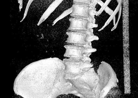
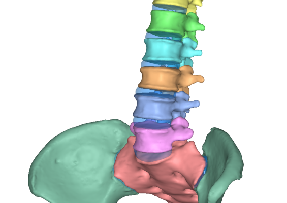
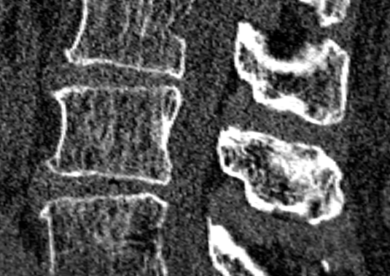
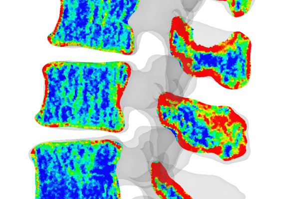
CT-based Modeling
Since 3D model can be constructed from DICOM data, it is possible to reflect the patient-specific bone geometry to the model. You can create 3D model by extracting region of interest (ROI) such as bone from CT data by image processing or manual correction. In addition, AI segmentation for hip and spine is available from version 12. Because it is a computer model, you can easily create osteotomy models and bone defect models.
* Uemura K, et al. Arch Osteoporos. 2022, Payer C, et al. VISAPP 2020, Uemura K, et al. Arch Osteoporos. 2023, Cheng Z, et al. JSMBE 2020
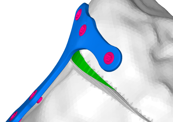
Implant Installation

You can import geometries such as implants in STL format as well as geometries constructed from CT data. The position of the implant can be adjusted while displaying surrounding CT images. In addition, you can set the axis and rotation center of the STL data, and by using it, it is possible to replace the installed screw by one with different length.
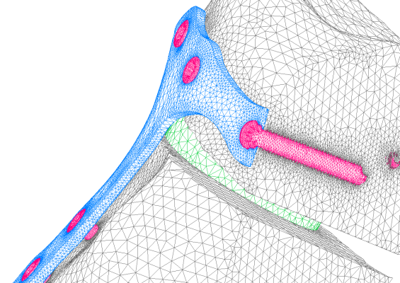
Automatic Meshing
MECHANICAL FINDER has a highly robust and size-controllable mesh generator based on fTetWild*1,2. Just specifying the mesh size, you can automatically generate a tetrahedral mesh. Even if various geometries overlap complicatedly, such as bones, and soft tissues, implants, boundaries between them are extracted accurately.
*1 Yixin Hu, et al. ACM Trans. 2020
*2 ANSYS ICEM CFD is also available.
Shell and Truss Element

In addition to tetrahedral elements, you can set shell elements and truss elements. Truss elements can be defined by strain-tension relationship, and it is useful for modeling ligaments where force works only in the tensile direction.
Inhomogeneous Material
Finite element analysis of bone has often been performed with homogeneous models or two-layer models consisting of cortical and cancellous bone. However, inhomogeneity of material properties is very important to evaluate bone stress, fracture, and instability of inserted implants, etc., therefore the analysis using inhomogeneous materials is now becoming the mainstream.
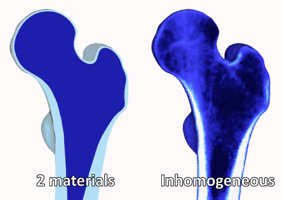
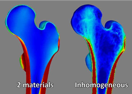
The CT value is converted to density, then each material property such as Young’s modulus is converted from density by referring to papers.
In MECHANICAL FINDER, since the solver and post-processing have been developed assuming inhomogeneous materials, there is no limit on the number of bone material properties. All tetrahedral elements can be assigned material properties based on the CT values at their positions.
Load Condition
To set the load condition, you can set the direction based on the preset axis. It is convenient to align conditions between analyses with different CT. In addition, when you set muscle force by load, you can also set the direction of it to always point from the origin to the insertion even if the bone positional relationship changes.

Forced Displacement

Forced displacement also can be set. When expressing cadaver experiments such as compression test and screw pullout test in finite element analysis, it is used for setting boundary conditions.
Material Nonlinear Analysis
In addition to elastic analysis, you can also perform material nonlinear analysis which deal with the plasticity and fracture of elements. To evaluate clinical fractures it is necessary to define a fracture in finite element analysis, but it is often found as bone strength from the displacement-load curve. There are some papers about cadaveric experimental validation of finite element analysis.

Geometric Nonlinear Analysis

Not only analysis based on Small deformation theory but also geometric nonlinear analysis is available. Especially in analysis with large deformation and rotation, analysis can be performed accurately by geometrical nonlinear analysis. Also, soft tissue such as intervertebral disc can be modeled as superelastic element.
Dynamic Analysis
In addition to static analysis, dynamic analysis which takes account in inertial force can be performed. By giving the initial velocity or setting the time-varying load, you can analyze phenomena occurring in a short time such as collision and impact.

Contact Analysis

Contact condition can be set on the boundary of materials such as bone and implants. It can be also set between multiple materials, and the friction coefficient can be set on the contact surface. By using the contact condition, it is possible to create a more realistic model such as the boundary between a stem and a femur just after THA surgery.
Results
Various results such as contour map of stress distribution and fracture map can be displayed: Deformation map / Contour map / Vector map / Tensor map / Fracture map / CT display. In addition, since it is possible to extract elements or nodes in region of interest and output data of all the extracted elements or nodes in CSV format, you can use it as editing or taking statistics with Excel.
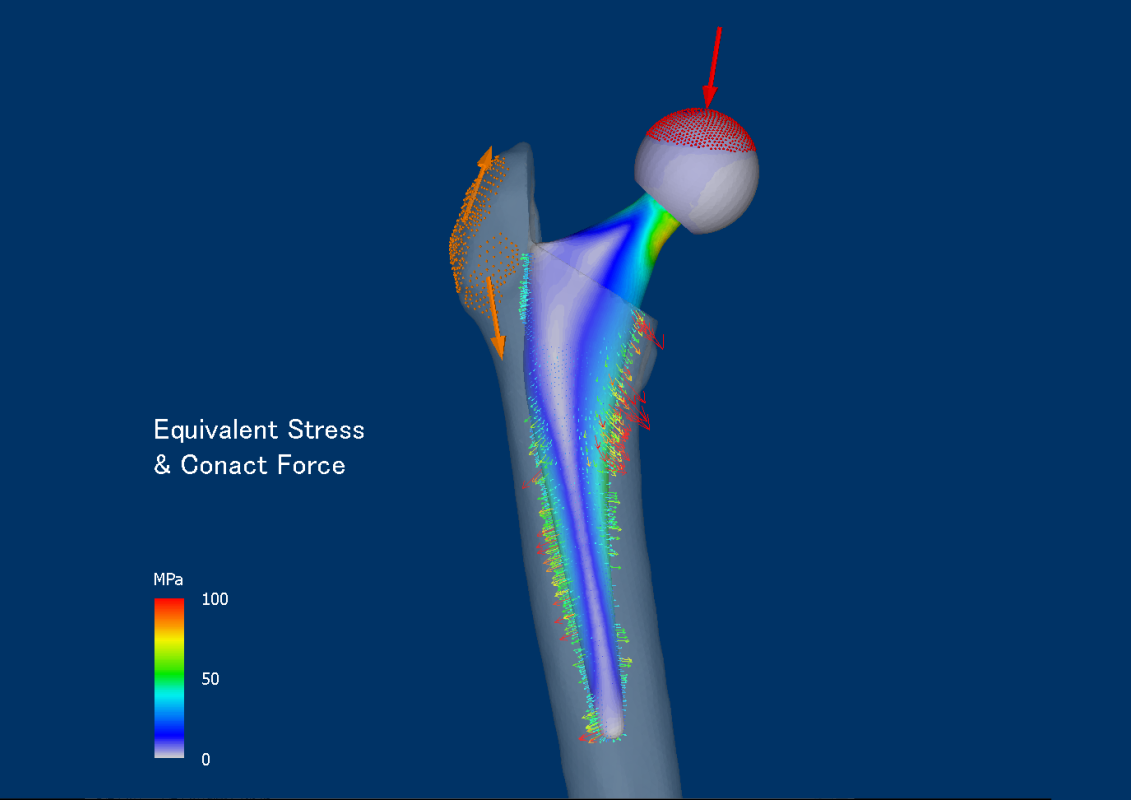
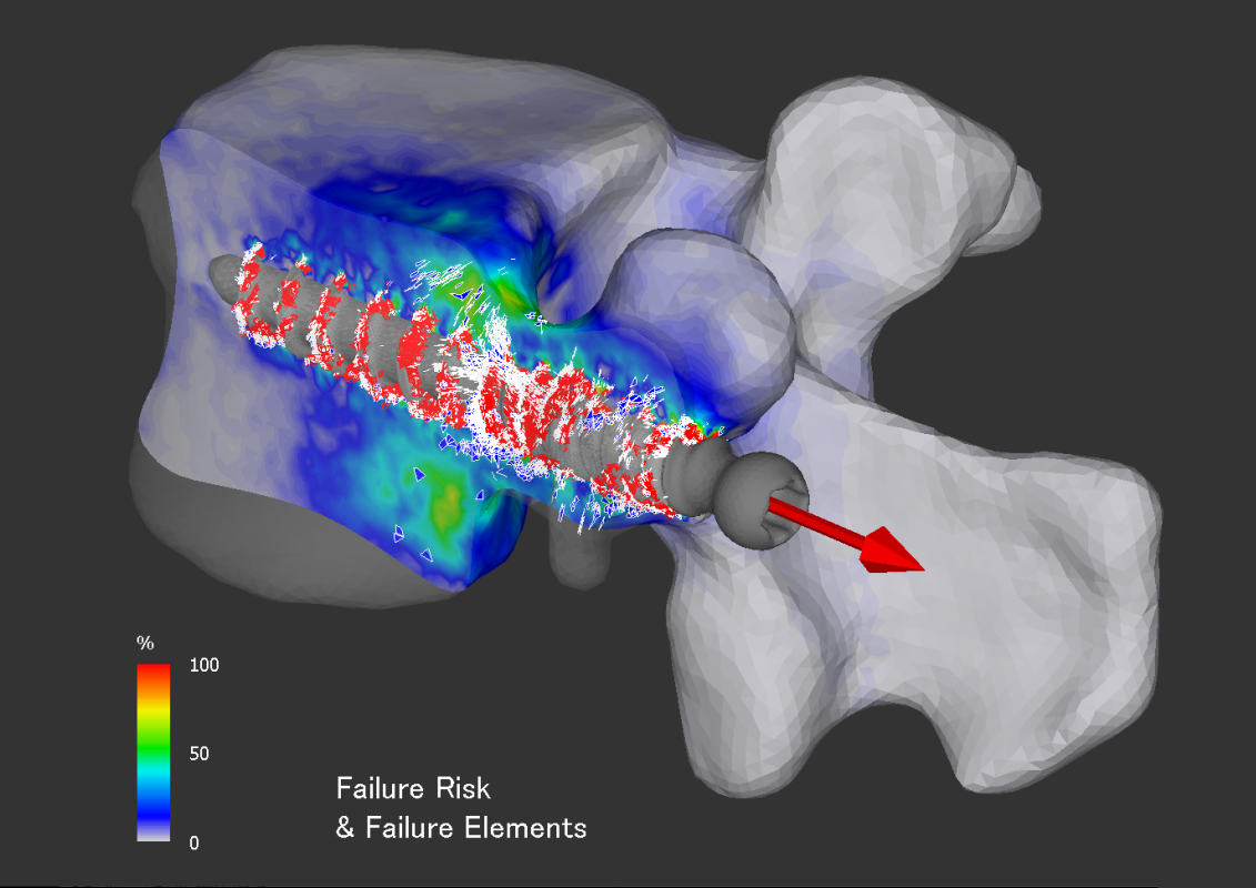
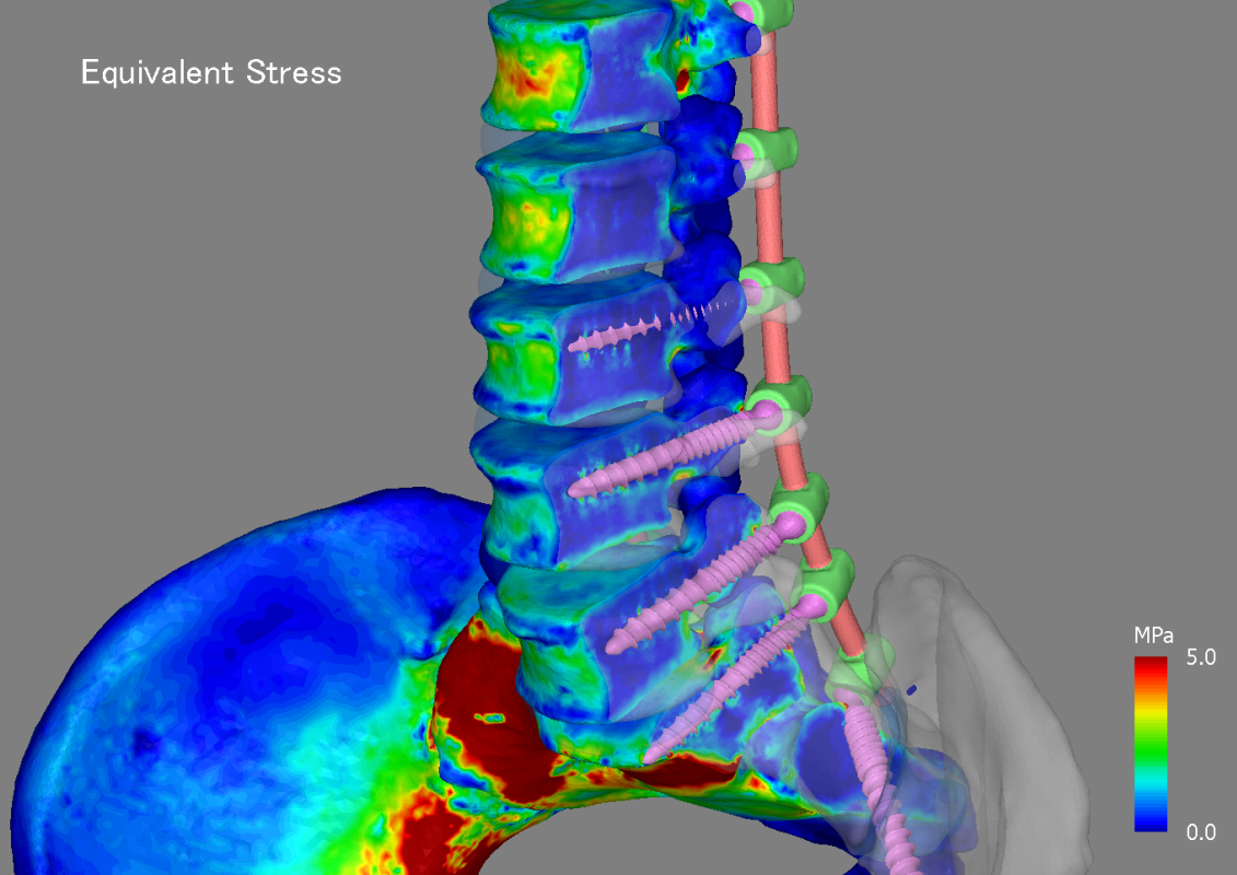
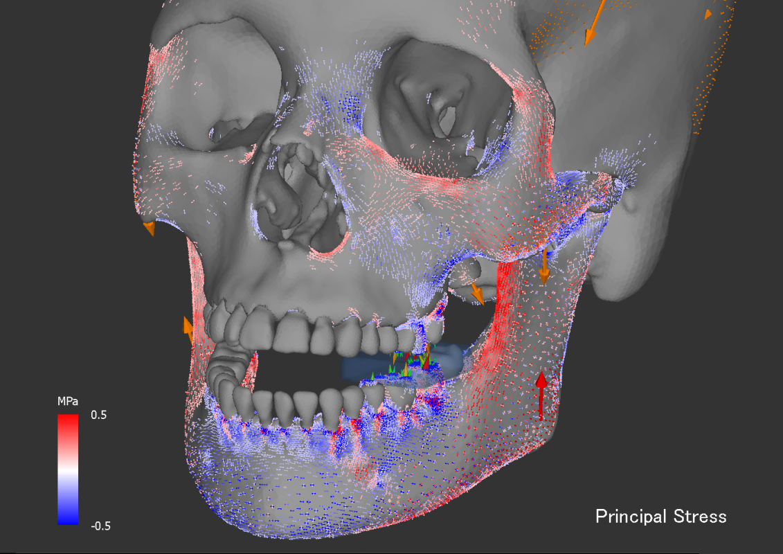
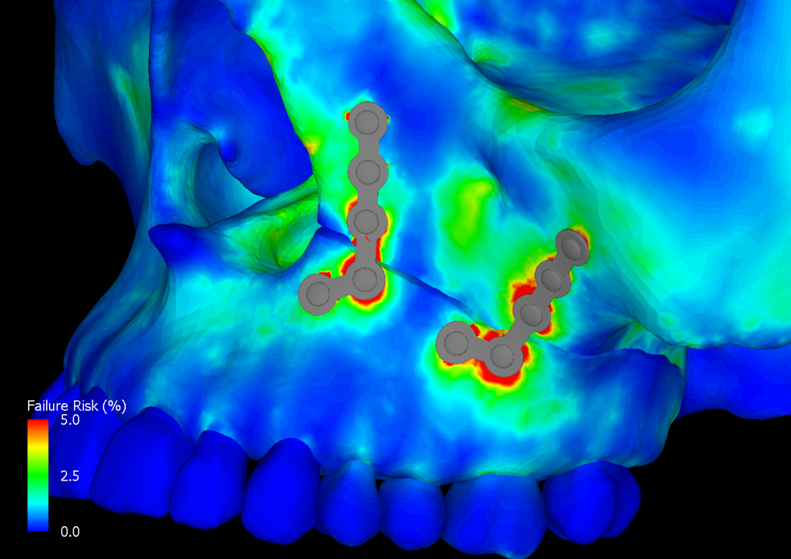
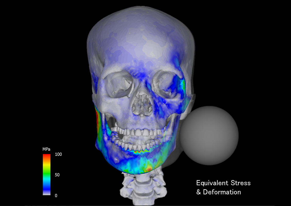
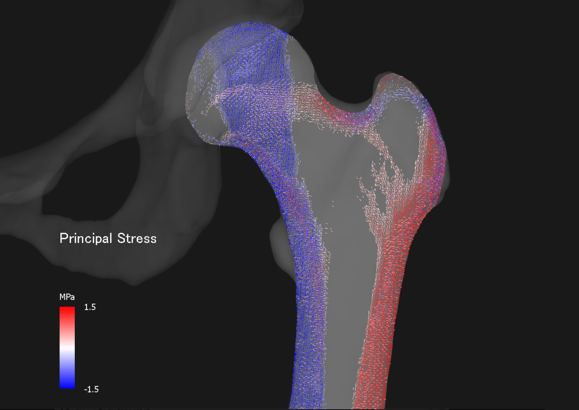
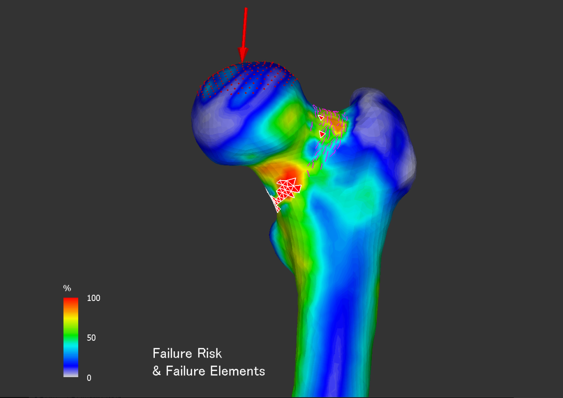
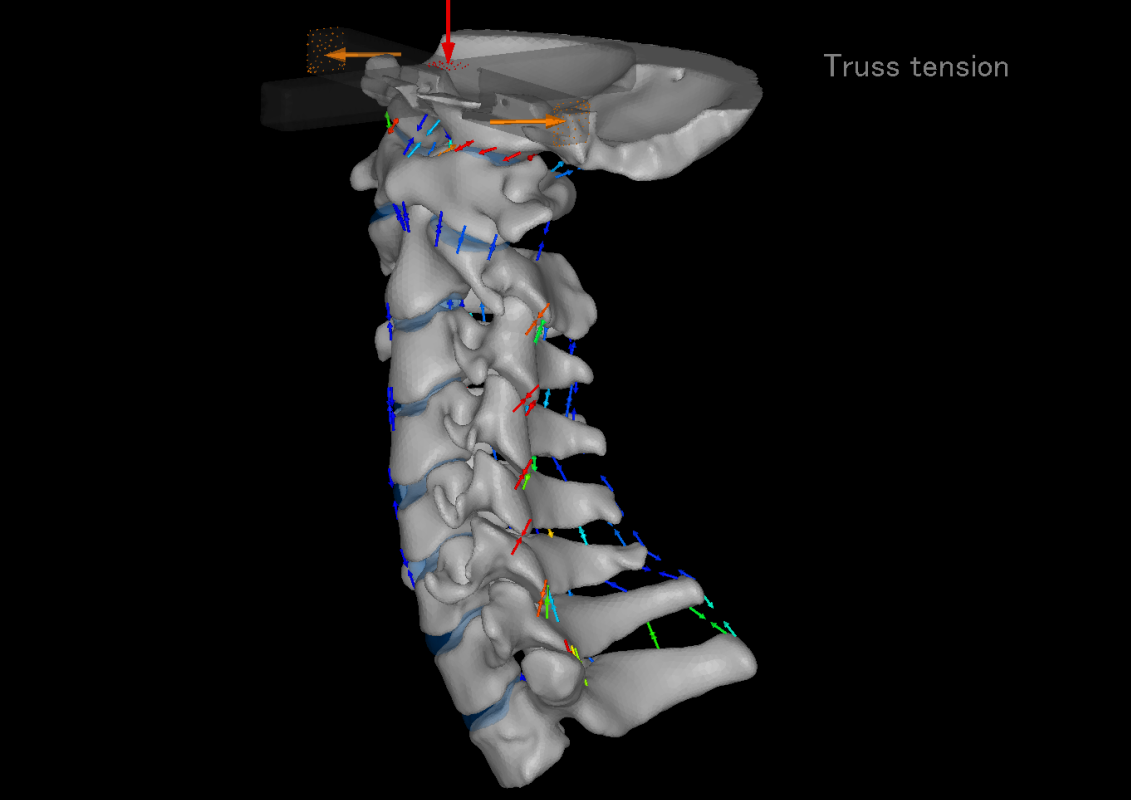
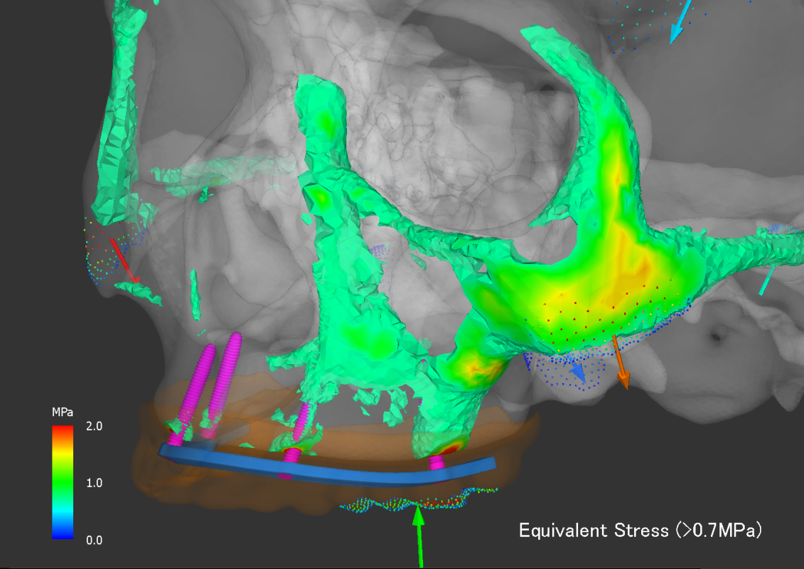
Image & Video

You can save the visualization frame as an image at each step such as material property and result screen. It also has a function to save the viewpoint, which is convenient when comparing results of different implant models. You can also save multiple frames as a video file. The videos of this web page are created using this function.
Geometry
You can output the geometry generated from the ROI extraction data, the placed geometry after importing, and the surface mesh after generating the tetrahedral mesh in the STL format. It can be used when reusing geometry extracted from CT in other models or when creating cut bone geometry once for osteotomy model.

